")
Rubberexpansionjoint.com DA style molded dual arch rubber expansion joints are designed to absorb movements and stress on piping systems, compensate for pipe misalignment, reduce vibration and system noise. The style DA protects against start-up forces as well as system surges. All DA style joints come standard with ANSI 150# solid floating metallic flanges and metallic root rings. The design of the DA style does not contain any metallic reinforcement in the carcass of the bellows. Instead the carcass has a minimum of four layers of high tensile synthetic fabric. Each layer is impregnated with a rubber or synthetic compound. This allows movement and flexibility between the layers of fabric. The DA style design has a long radius arch allowing for self cleaning and thus eliminating the need for a filled arch. The DA style is the most economic choice when it comes to dual arch rubber expansion joints. The DA is available on request to meet the requirements of the U.S.C.G.
| DUAL ARCH (DA) | |||||||||||||||
|---|---|---|---|---|---|---|---|---|---|---|---|---|---|---|---|
| Diminsions | Movement Distance | Operating Condition | Weight (LBS) | ||||||||||||
| Pipe Size | O'all Length | Flange OD | Bolt Circle | Flange Thickness | No. of Bolt Holes | Bolt Hole Size | Threaded Hole Size | Axial Compression | Axial Extension | Lateral Deflection | Angular Deflection | Max w.p. (psi)-3,-4 | Max Vacuum (in. of Hg)-5 | Exp. Joint + Flanges | Control Unit (2 Rod)-1,-2 |
| 1" | 5" | 4 1/4" | 3 1/8" | 0.55" | 4 | 5/8" | 1/2"-13 | 2" | 1.188" | ±1.75" | 45° | 225 | 26 | 4.00 | 5.50 |
| 1 1/4" | 7" | 4 5/8" | 3 1/2" | 0.55" | 4 | 5/8" | 1/2"-13 | 2" | 1.188" | ±1.75" | 45° | 225 | 26 | 5.25 | 5.50 |
| 1 1/2" | 7" | 5" | 3 7/8" | 0.55" | 4 | 5/8" | 1/2"-13 | 2" | 1.188" | ±1.75" | 45° | 225 | 26 | 6.00 | 5.50 |
| 2" | 7" | 6" | 4 3/4" | 0.63" | 4 | 3/4" | 5/8"-11 | 2" | 1.188" | ±1.75" | 45° | 225 | 26 | 8.50 | 6.75 |
| 2 1/2" | 7" | 7" | 5 1/2" | 0.71" | 4 | 3/4" | 5/8"-11 | 2" | 1.188" | ±1.75" | 43° | 225 | 26 | 11.25 | 8.00 |
| 3" | 7" | 7 1/2" | 6" | 0.71" | 4 | 3/4" | 5/8"-11 | 2" | 1.188" | ±1.75" | 38° | 225 | 26 | 13.75 | 8.00 |
| 4" | 9" | 9" | 7 1/2" | 0.71" | 8 | 3/4" | 5/8"-11 | 2.25" | 1.375" | ±1.562" | 34° | 225 | 26 | 19.25 | 7.50 |
| 5" | 9" | 10" | 8 1/2" | 0.79" | 8 | 7/8" | 3/4"-10 | 2.25" | 1.375" | ±1.562" | 29° | 225 | 26 | 22.50 | 8.00 |
| 6" | 9" | 11" | 9 1/2" | 0.87" | 8 | 7/8" | 3/4"-10 | 2.25" | 1.375" | ±1.562" | 25° | 225 | 26 | 28.00 | 9.00 |
| 8" | 13" | 13 1/2" | 11 3/4" | 0.87" | 8 | 7/8" | 3/4"-10 | 2.5" | 1.375" | ±1.375" | 19° | 225 | 26 | 46.00 | 13.00 |
| 10" | 13" | 16" | 14 1/4" | 0.95" | 12 | 1" | 7/8"-9 | 2.5" | 1.375" | ±1.375" | 15° | 225 | 26 | 63.00 | 25.25-1 |
| 12" | 13" | 19" | 17" | 0.95" | 12 | 1" | 7/8"-9 | 2.5" | 1.375" | ±1.375" | 13° | 225 | 26 | 88.00 | 28.01-1 |
| 14" | 13.75" | 21" | 18 3/4" | 1.02" | 12 | 1 1/8" | 1" -8 | 1.75" | 1.118" | ±1.118" | 9° | 150 | 26 | 119.00 | 33.55-1 |
| 16" | 13.75" | 23 1/2" | 21 1/4" | 1.10" | 16 | 1 1/8" | 1" -8 | 1.75" | 1.118" | ±1.118" | 8° | 150 | 26 | 147.00 | 41.00-2 |
| 18" | 13.75" | 25" | 22 3/4" | 1.18" | 16 | 1 1/4" | 1 1/8" -7 | 1.75" | 1.118" | ±1.118" | 7° | 150 | 26 | 158.00 | 43.50-2 |
| 20" | 13.75" | 27 1/2" | 25" | 1.18" | 20 | 1 1/4" | 1 1/8" -7 | 1.75" | 1.118" | ±1.118" | 7° | 150 | 26 | 185.00 | 44.50-2 |
| 24" | 13.75" | 32" | 29 1/2" | 1.18" | 20 | 1 3/8" | 1 1/4" -7 | 1.75" | 1.118" | ±1.118" | 5° | 150 | 26 | 211.00 | 62.50-2 |
-
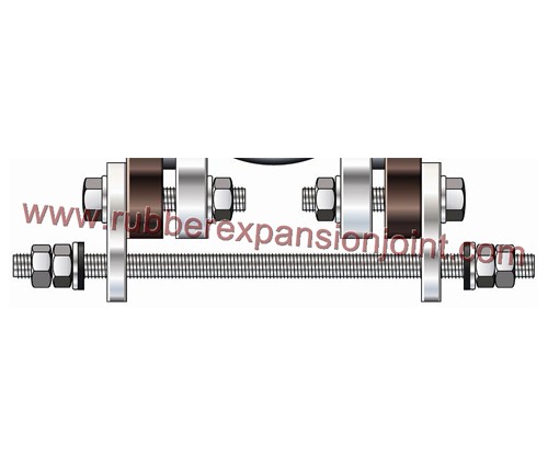
LR-96-L
$45.606 IN CONTROL UNIT * LIMIT ROD STYLE (LONG) * ALL CS ZINC PLATED COMPONENTS * 2 ROD SET Learn More
